Manual Transfer Switch Wiring Diagram: A Comprehensive Guide
When it comes to ensuring the safety and efficiency of your electrical systems, a manual transfer switch is an essential component. This crucial device allows you to switch between primary and backup power sources seamlessly, ensuring that your critical systems remain operational even during power outages. In this article, we will delve into the intricacies of manual transfer switch wiring diagrams, providing you with a comprehensive guide to help you navigate the process effectively. Whether you are a seasoned electrician or a DIY enthusiast, this guide will equip you with the necessary knowledge to successfully install and maintain your manual transfer switch.
Understanding the Wiring Diagram
Before diving into the wiring process, it is crucial to comprehend the manual transfer switch wiring diagram. This diagram serves as a blueprint for the entire installation, outlining the connections and configurations required for a safe and efficient operation. By following the diagram carefully, you can avoid common mistakes and ensure that your system functions as intended. In the following sections, we will break down the key components and steps involved in the wiring process, providing you with a step-by-step guide to successful installation.
what is a manual transfer switch and how does it work
 A manual transfer switch is an electrical device used to switch power sources between the main utility supply and a backup generator or alternate power source. It is designed to ensure a safe and efficient transition of power during a power outage. Here’s how it works:How a Manual Transfer Switch WorksA manual transfer switch connects the house’s electrical circuits to the generator. During a power outage, you can use it to switch on the backup power. Any appliance connected to the circuit will run on backup power until electricity is restored. The manual transfer switch can be installed both indoors and outdoors, depending on the generator’s power output and the specific installation requirements.Key Features and Benefits
Easy Operation: The switch can be operated manually by moving a lever or button, allowing you to shift the load to the generator with ease.
Full Control: You have complete control over when to use the generator for temporary power supply.
Cost-Effective: Manual transfer switches are generally less expensive to install and maintain compared to automatic transfer switches.
Safety: It is safer than extending power cords from the home to the generator, as it connects the generator directly to the circuits.
Installation and OperationTo install a manual transfer switch, you need to connect it to the main electrical circuit panels and wire it to a power inlet box. The generator connects to the power inlet box during a power cut. A professional electrician typically completes the wiring and installation process.Steps to Operate a Manual Transfer Switch
Turn off circuits: Switch off the circuits in the transfer switch.
Connect the generator: Use a gen cord to connect the manual transfer switch with the generator.
Start the generator: Start the generator and let it warm up.
Switch to generator: Change the transfer switch from ‘Line’ to ‘Generator’ to shift the power load.
Turn on circuits: Turn on the circuits that you wish to power through the generator backup. Avoid overloading the generator.
Switch back to line: When electricity is restored, change the manual transfer switch from ‘generator’ to ‘line’ to shift the power supply.
Disconnect the generator: Switch off the generator
what are the different types of transfer switches
 There are several types of transfer switches, each designed to serve specific purposes and applications. Here are the main types:
Manual Transfer Switch: This type of transfer switch requires manual operation by an operator. It is typically used for simple applications where the transfer switch is easily accessible and the power source is not critical. Manual switches are relatively simple and inexpensive but may not be suitable for safety-critical applications where quick switching is necessary.
Non-Automatic Transfer Switch: This type of transfer switch is manually initiated but electrically operated. It is used when the transfer switch is difficult to access or when there are multiple transfer switches to operate. The decision to switch power sources remains in human hands.
Automatic Transfer Switch (ATS): This type of transfer switch operates automatically without human intervention. It includes a smart controller that detects power outages and automatically starts the standby generator and switches to it. The controller can be programmed to react to specific grid changes or custom triggers. Automatic switches are commonly used in critical applications where quick and reliable switching is necessary.
Bypass Isolation Transfer Switch: This type of transfer switch includes an automatic transfer switch and a bypass switch. It allows the capability to transfer the load to the bypass switch without interrupting power. This type of switch is used for specific applications, such as UPS systems.
Soft Load Transfer Switch: This type of transfer switch is designed for applications where a smooth transition between power sources is necessary. It actively controls the generator voltage and frequency to ensure a seamless transfer. This type of switch is used in applications where a “bump-less” transfer is required.
Closed Transition Switching / ‘Bump-less’ Switching: This type of transfer switch is designed for applications where a smooth transition between power sources is necessary. It ensures that there is no break in power during the transfer. This type of switch is used in applications where a “bump-less” transfer is required.
These types of transfer switches cater to different needs and applications, ensuring safe and efficient power transfer in various settings.
what is the difference between a manual and automatic transfer switch
A manual transfer switch and an automatic transfer switch are two types of devices used to switch power sources between the main utility supply and a backup generator or alternate power source. The primary difference between the two lies in their operation and functionality:
Manual Transfer Switch
Operation: A manual transfer switch requires human intervention to switch power sources. It is typically operated by flipping a switch or pressing a button to transfer power from the main utility supply to the backup generator.
Advantages:
Lower initial cost
Easier installation
Greater control over when to switch power sources
Disadvantages:
Longer downtime during power outages
Requires a skilled operator to operate safely and efficiently
Less suitable for critical applications where quick switching is necessary
Automatic Transfer Switch
Operation: An automatic transfer switch operates without human intervention. It detects power outages and automatically starts the standby generator and switches to it.
Advantages:
Faster operation
Higher capacity for handling larger electrical systems
Suitable for critical applications where quick and reliable switching is necessary
Disadvantages:
Higher initial cost
May waste some energy due to false signal detection
More complex design and additional functionalities
In summary, manual transfer switches are more suitable for smaller applications, such as homes or small businesses, where control over power switching is important but downtime is not critical. Automatic transfer switches are better suited for larger settings, such as industrial or commercial applications, where quick and reliable switching is essential to minimize downtime and ensure continuous operation.
A manual transfer switch is installed next to the main service panel to override the normal electrical service with power from a backup generator during a power outage. On January 15 2022.

Diagrama De Cableado De Un Generador Portatil Al Hogar Manual Del Interruptor De Transferencia Del Ge Transfer Switch Generator Transfer Switch Generator House
They transfer power automatically to the generator source and switch back to utility power when it is restored.

Manual transfer switch wiring diagram. A wiring diagram is a simplified conventional photographic representation of an electric circuit. You can locate this manual easy to make use of and in addition really affordable. Figure 5 – Wiring Diagram Of A Manual Transfer Switch In The ON Position When utility power is functioning the wires from the circuit breaker in the main electrical distribution panel are connected to the generator sub-panel.
Ats Automatic Transfer Switch Panel 3ph 110a Ac1 Generator Auto Start Output. Reliance generator transfer switch wiring diagram gentran power stay indoor manual transfer switch wiring diagram. A wiring diagram is a simplified conventional pictorial depiction of an electrical circuit.
Winco square d manual transfer switch ez connect automatic backup generator auto wire diagram house 7225 7426 ronk switches with rotary wiring q midwest electric breakers psi 01 200 amp. Manual transfer switches require an operator to change the power source while automatic switches detect the loss of power start the backup generator and switch over to the backup power feed. Manual Transfer Switch Wiring Diagram 100 amp manual transfer switch wiring diagram 200 amp manual transfer switch wiring diagram 3 phase manual transfer switch wiring diagram Every electrical structure consists of various different parts.
Strip 58 and insert into an unused hole in the Neutral bar. However it doesnt imply connection between the cables. Single Phase Manual Changeover Switch Wiring Diagram One of the most hard automotive fix tasks that a mechanic or repair shop can take is the wiring or rewiring of a cars electrical system.
Follow this procedure for each of the remaining circuits. Start the generator outside. Turn ON main circuit breaker in transfer switch.
Wiring Diagrams September 25 2021 1207. It includes directions and diagrams for different varieties of wiring techniques as well as other products like lights home windows and so on. Plug in female connector to bottom of inlet box.
Automatic transfer switch amp single phase vac service rated circuit load center 28 pages Switch Generac Power Systems RTSWG3 Owners Manual Automatic transfer switch – amp three phase service entrance 32 pages. Find the Green wire from the transfer. Trim 58 inch 159 cm from the covering of each individual wire.
Wiring Diagram Pictures Detail. It is also shows the working and operation for different changeover switches wiring connections like single phase manual changeover switch with generator three phase manual transfer switch connection with generator as well as. With the aid of this guide youll be able to effortlessly do your own personal wiring tasks.
It reveals the parts of the circuit as simplified shapes as well as the power and also signal links between the devices. Assortment of manual transfer switch wiring diagram. Assortment of manual transfer switch wiring diagram.
Manual transfer switches require an operator to change the power source while automatic switches detect the loss of power start the back-up generator and switch over to the backup power feed. Following aggravating to remove replace or repair. According to earlier the traces at a Manual Transfer Switch Wiring Diagram represents wires.
7205a 7215 Ronk Manual Transfer Switch 200a 250v Single Phase 2 Pole Aluminum Outdoor Enclosure. Manual Generator Transfer Switch Wiring Diagram Wiring Diagram Manual Transfer Switch Wiring Diagram. A wiring diagram is a simplified traditional pictorial depiction of an electric circuit.
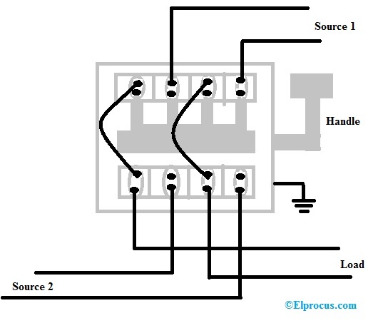
Sometimes the wires will cross. Manual Transfer Switch Wiring Diagram. Generac Manual Transfer Switch Wiring Diagram Download Electrical Manual Changeover Switch Wiring Diagram For Portable Generator Manual changeover switch are mostly use in 2 types in which one have the move able knob and 2nd one the handle changeover switch.
Figure 4 Wiring Diagram Of A Manual Transfer Switch In The Off Position Figure 5 Wiring Diagram Of A Manual Transfer Switch In The ON. Figure 5 Wiring Diagram Of A Manual Transfer Switch In The ON Position. Injunction of two wires is generally indicated by black dot to the intersection of 2 lines.
Figure 1 generator transfer switch the transfer switch is the device that transfers the power from the utilities power to the standby generators power as shown in figure 1. Affix the transfer switch to the wall using mounting screws. February 15 2021 on Generator Transfer Switch Wiring Diagram.
It reveals the components of the circuit as streamlined forms and also the power as well as signal connections in between the gadgets. Wiring Diagram Images Detail. Wiring DiagramSchematic A V Drawing No.
Rv Transfer Switch Wiring Diagram Wiring Diagram Transfer Switch Wiring Diagram. Guardian Generator Transfer Switch Wiring Diagram Manual E-Books Generac Transfer Switch Wiring Diagram. Find the White wire from the transfer switch.
Turn OFF all circuit breakers in transfer switch and load center. Insert Male plug into generator. This can be beneficial for each the folks and for specialists whore looking to find out more on how to set up a operating surroundings.
150 Kw Transfer Switch Wiring Diagram For Auto Wiring Diagrams Lose Transfer Switch Wiring Diagram. Test By Transferring From Utility to Generator Power. Desired wire from the transfer switch using wire connectors.
Youll be able to always depend on Wiring Diagram being an crucial reference that may enable you to conserve time and money. Blue connected using wirenuts to the wire removed from the breaker. Switch Wire Conductor Tightening Rating Range Torque A.
Pull the bundle of wires through the insulating tube. January 15 2022 on Manual Transfer Switch Wiring Diagram. Each component ought to be set and connected with different parts in particular manner.
Standard Diagrams Transfer between 3 sources – 2 Bus bars continued Implementation Compacity built in solution Plug and play Mechanical and electrical interlocking are in build Operation Only 2 or 3 emergency handles instead of 4 or 5 A motorized switch can be added on the Non Critical Loads for optional disconnection. The transfer switch should be placed roughly 1 12 feet 4572 cm away from the midpoint of the main circuit breaker. Wiring Diagram consists of both examples and step-by-step instructions that will permit you to really construct your project.
In our step by step electrical wiring installation tutorials series We will show how to wire and connect single phase and three phase automatic and manual changeover and transfer switches to the home distribution board to use the backup power supply such us batteries power with UPS and inverters or generator power in case of emergency breakdown and power outage. Wiring Diagrams are made to be easy to comprehend and easy to create. Wiring Diagram includes numerous in depth illustrations that show the connection of varied things.
The problem in reality is that all car is different. Otherwise the structure will not work as it.
Manual Changeover Switch Wiring Diagram For Portable Generator Transfer Switch Generator Transfer Switch Electrical Circuit Diagram

Generac Manual Transfer Switch Wiring Diagram Transfer Switch Generator Transfer Switch Wire
Thank you for taking the time to read our comprehensive guide on manual transfer switch wiring diagrams. We hope that the detailed explanations and examples provided have been helpful in understanding the intricacies of this crucial component in ensuring the safety and efficiency of your electrical systems. Whether you are a seasoned electrician or a DIY enthusiast, we believe that this guide has equipped you with the necessary knowledge to successfully install and maintain your manual transfer switch.
As you continue to navigate the world of electrical engineering, we encourage you to stay informed about the latest developments and best practices in the field. Remember that a manual transfer switch is an essential component in ensuring seamless power transfer during power outages. By following the guidelines outlined in this article, you can ensure that your system functions efficiently and safely. If you have any further questions or concerns, please do not hesitate to reach out to us. We are always here to help. Thank you again for your interest in our article, and we wish you continued success in your endeavors.
what are the key takeaways from the article on manual transfer switch wiring diagram
The article on manual transfer switch wiring diagram provides several key takeaways:
Location and Installation: The transfer switch should be located as close as possible to the engine generator or alternate power source, with a clear line of sight between the switch and the generator. Ensure that the normal, emergency, and load isolation switches are open before making connections.
Wiring Connections: Connect the load, normal source, and emergency source power cables in the same phase sequence. Refer to the latest NFPA 70 and Field Connections Wiring Diagram for cable sizes and torque requirements.
Maintenance and Inspection: Regularly inspect the transfer switch for debris and moisture. Use a clean cloth or vacuum to prevent debris from lodging in the switching mechanism. Check all wiring connections and visually inspect the contacts for surface deposits and pitting annually.
Testing: Perform a manual and automatic transfer test after installation and each week thereafter. The manual test involves disconnecting the emergency and normal power sources before transferring with the handle.
Compatibility: Ensure that the transfer switch is compatible with the load. Refer to the receiving, handling, storage, installation, and inspection procedures in the Instruction Manual that accompanies the combination Fire Pump Controller and automatic transfer switch.
Schematic and Wiring Diagrams: Refer to the schematic and wiring diagrams provided with the transfer switch, which are included in a packet along with the manual. These drawings are also posted on the inside of the cabinet door.
Automatic Operation: The transfer switch can automatically switch to the emergency source during a power outage. The Control Module monitors the normal source phase voltage for acceptable limits of drop-out and pick-up.
Manual Operation: Manual operation of the transfer switch is only for testing the mechanical operating mechanism or switching when there is a control problem. It involves sliding the square notch at the end of the handle.
These key takeaways highlight the importance of proper installation, maintenance, and testing of manual transfer switches to ensure seamless power transfer during power outages.
Keywords : Electrical System,Manual Transfer Switch Wiring Diagram,Manual Transfer Switch,Automatic Transfer Switch,Power Transfer Switch

